Please remember this is a work in progress and we’ve just created this page on the fly!
The Raspberry Pi
The Raspberry Pi just runs one of the stock images available from the RaspberryPi.org site (Raspbian “wheezy”). On top, we’ve chucked Nginx and PHP. We’ve not given instructions on how to do the Nginx and PHP as a quick Google search shows enough information to allow you to do this 🙂 (You’ll notice that a lot of the content here simply says “Go Google”. Sorry about that!).
At this point you should make yourself aware of the GPIO pins on the Pi. Print out the schema so that you have it to reference: http://elinux.org/RPi_Low-level_peripherals
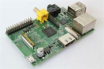
You can see the GPIO pins on the top left of the Pi
The Relay and the Remote
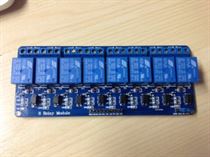
The relay board connects to the Pi using the pin outs. You’ll need to connect GND to a Ground pin on the Pi, and the VCC pin to the 5v pin on the Pi. From there, you have IN1, IN2, etc. which are just Relay 1, Relay 2 etc. respectively. Don’t change the jumper on the relay board, it should be set to VCC JD-VCC.
The Relay board is pictured below (click on it to see the full size image):
It was bought from Ebay via this link: http://www.ebay.co.uk/itm/New-5V-8-Channel-Relay-Module-Board-for-Arduino-PIC-AVR-MCU-DSP-ARM-Electronic-/170745298865?pt=UK_BOI_Electrical_Components_Supplies_ET&hash=item27c1367fb1
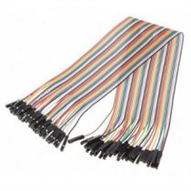
To make life easier (we originally ripped apart a floppy ribbon and it got verrrry messy and verrrry confusing for the brain!) you should probably buy these individual jumper wires below. The colour coded nature of them makes life easier when connecting between the Pi and the Relay board.
We bought ours from Hobby Tronics in the UK: http://www.hobbytronics.co.uk/ribbon-jumper-female-40?keyword=40JUMPERF
Last thing you’ll need is the remote control set we used. These are just plugs you connect to a wall socket and then pair with the remote control. For safety reasons we decided this was a better way to go about things rather than splicing mains cables into the relay board. It actually worked out even better as it meant we could position lights anywhere in the room without having to trail loads of wiring to the relay board.
Here’s a crude image of the box. We bought a cheap one from a local retail shop for £20. Fair word of warning here: We actually bought a different set to begin with, but the remote control PCB itself was horrible for soldering the wiring from the relays. Rather than buttons it had rubber electrodes that made the connection between the tracks on the PCB itself. This second set actually used proper switches, so it was easy to solder the connection into the appropriate hole in the PCB.
Each channel (there’s four channels to choose from) needs two relays to control. One sends the ON signal, and one sends the OFF signal.
So for example, here’s the PHP script for turning ON channel 1, which happens to be connected to GPIO4.
if( isset($_POST[‘action’]) )
{$a = $_POST[‘action’];
if($a==”on”) {
exec(‘echo “0” > /sys/class/gpio/gpio4/value’);
sleep(0.75);
exec(‘echo “1” > /sys/class/gpio/gpio4/value’);
}
The first three lines are just checking that we’ve got a POST request coming in. The second if statement is checking that we’re turning the device ON. And then we set the signal on the GPIO4 pin. We echo 0 (which for some reason sets the pin live… I don’t know why), we wait 0.75 seconds to give the remote control unit time to send the wireless signal, and then we switch the relay off by echoing 1 to the same GPIO pin. There! The device is on!
To switch it off, you do the exact same, but wire up another GPIO to another Relay Switch, and then from there to the Off button on the Remote 🙂
Video
The video is just an RTMP-enabled web cam (It’s an Axis M1011, get it here ). The stream is picked up by Wowza broadcast software on an Amazon EC2 box.
This is then played via the website using JWPlayer (http://www.longtailvideo.com/jw-player/). It really is that simple! By allowing an Amazon EC2 box to provide the stream, it lessens the load on the web server providing the main content.
Chat
Nothing exciting about the chat to be honest, it’s just a copy of PHPFreeChat (get this here: http://www.phpfreechat.net/) tweaked to look nice within the design of our page. We were prepared to look at alternative chat methods should the load become an issue. An IRC server could have been set up within 15 minutes to lessen the load of the chat script. But at the time of writing, this wasn’t necessary.
The Code (Raspberry Pi end)
For each GPIO output, you need to set it up. We Googled, we found this:
echo $pin > /sys/class/gpio/export
echo “out” > /sys/class/gpio/gpio$pin/direction
We then chmod the specific pin to 777 (so that php/nginx can happily go about changing values):
chmod 777 /sys/class/gpio/gpio$pin/value
It’s important to remember that $pin equates to one of the valid GREEN GPIO numbers from the schema. 4, 17, 22, etc. so re-write this as appropriate!
To make life easy, we added this to our /etc/rc.local file so that on boot, the Raspberry Pi would set up all the GPIO pins we were going to use:
echo “4” > /sys/class/gpio/export
echo “out” > /sys/class/gpio/gpio4/direction
chmod 777 /sys/class/gpio/gpio4/valueecho “17” > /sys/class/gpio/export
echo “out” > /sys/class/gpio/gpio17/direction
chmod 777 /sys/class/gpio/gpio17/valueetc. etc. etc. for all pins
Once you’ve got the relay hooked up, you can then go about testing the GPIO output:
echo “0” > /sys/class/gpio/gpio4/value
echo “1” > /sys/class/gpio/gpio4/value
If all is correct, you should see the LED on the Relay Board and hear the click of the Relay. It’s in your hands which way 0 or 1 goes with the relay (either on or off)!
The Code (The Queue System)
This is coming soon! It’s horribly horribly hacked together with two tables in a database. One is the Auth table (you get entered into this table when you log in with a username/Facebook) and a Queue table (this is populated when you click Join The Queue!). Lots of page refreshes later, the magic happens. More to follow!


